|
UPDATE - October
On the first posting of
'Mandalay' one of my closing passages was how straightforward it was just
to finish off the electrics. Converting the crane from wired remote to
wireless Remote Control was to be 'straightforward'. Oh, how wrong I
was!!!
After burning the candle till the early hours for several nights trying to
work out why I could not get to do what I wanted I had to resort to help
from a friend of my sons, Graham Lee. I explained what I wanted to do -
all I want is for the crane to go left/right, up/down, etc when I push the
transmitter switch. Graham said it was impossible without a bit of
electronics. He started talking about diodes and the what. Lost me
completely but I was so pleased when he kindly offered to draw me a
'simple' diagram and even gave me the 18 parts required.
The following day they arrived and I looked at the 'simple' diagram. Now I
thought I had a basic knowledge of electronics but I obviously didn't as
it confused me completely. Grateful for what he had done I tried
desperately to learn - to no avail. The following day I just happened to
mention it to a friend in work (it was probably the desperate look on my
face that gave it away) and he said his dad was an electronics engineer.
Enter Tony Gibbs!!!
Absolute doddle for him he said. In no time at all I received a circuit
board measuring abut 2'' x 1'' with all the components attached. He even
attached 12' wires to all 13 connections in different colours and drew me
an 'idiots' diagram that even I could follow. I am ecstatic to say the
least - it works brilliantly and I am looking forward to trying it out. I
did have a crazy idea of attaching a hook and float and going fishing with
it but I shall resist the temptation of maybe seeing my boat being dragged
into the sunset by a carp or pike.
So my extreme gratitude goes to Graham Lee and Tony Gibbs - thanks guys!!
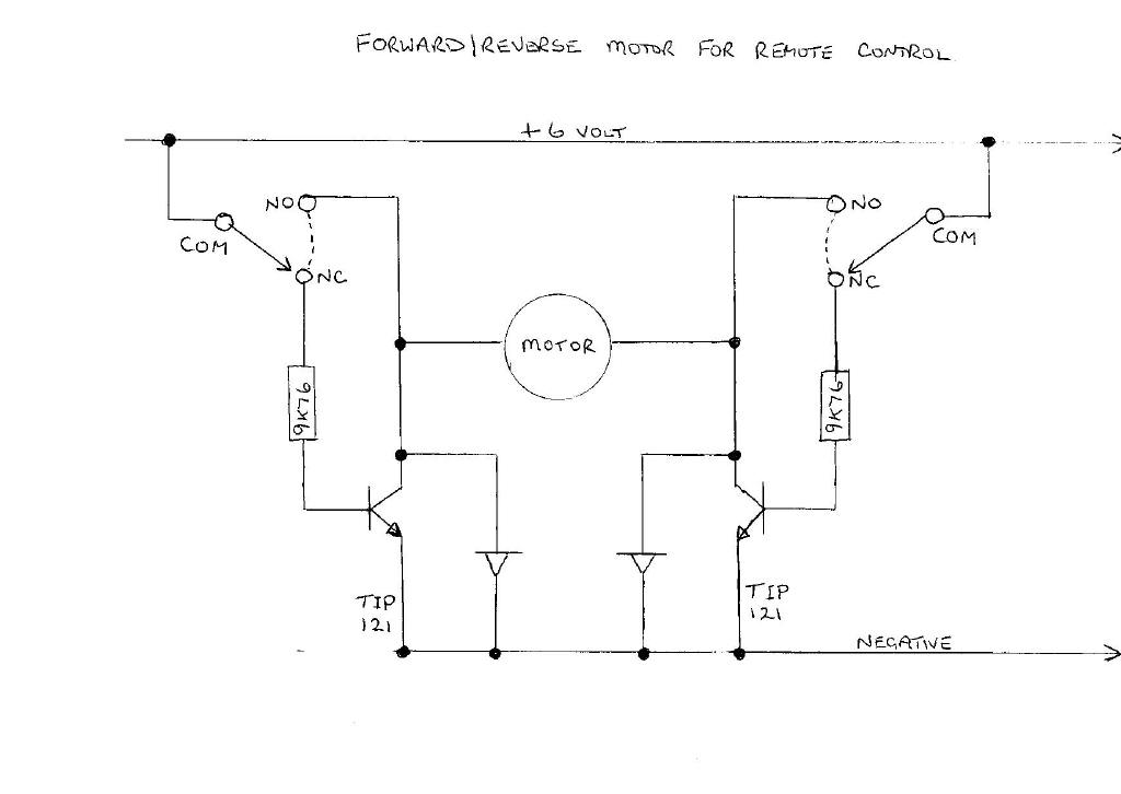
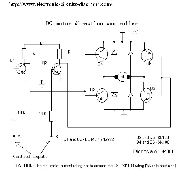
I have attached the diagram for auto reverse on any 6 volt motor with the
required components. I have also attached the photo of what it all looks
like in the frame.
The 2 switches are attached either side of the servo. Two arms go the
micro-switch and bent at 90 degree angles to run behind the roller to stop
them coming out, then soldered. When the servo is in neutral both switches
are off. Either way and it switches either one or the other on and remains
so till it is returned to central.
Although this used to guide the crane left and right, up and down and in
and out I suppose it could be used in a multitude of applications. I hope
someone can make use of it. maybe you would like to post it on the web
site for others as well - you are quite welcome to do as you wish.
Kind regards
Graham
 |
|
Hi Martin,
I have a home built boat on the site, which is currently having a major
upgrade due to a 'roll' on the lake. That's the price of taking my eye off
it while idle chatting (graham Voss-Barbie Boat).
Yes, I am still a novice but yes, I am still around and have built
another. I saw a free plan in Marine Modelling International (July 2004)
of a Dragonfly airboat. Excited at the prospect of not having my boat
going round and round in circles in the middle of the lake after picking
up weed, I decided to build it. Now I have never been one for conventional
build of anything. I used the plans as guide only. In fact, the only part
that was the same was the shape, motor and rudder.
I built the hull to the plan, except I used 4'' thick polystyrene sheet
from the builders yard because I knew I was going to load it with lots of
items. It was shaped and covered in brown paper, fixed with watered down
PVA glue to 50/50. When dry the whole thing was covered in Solartrim self
adhesive and stretched with a hair dryer to take out the wrinkles.
The topside was cut out both front and rear. The front houses the 8.4
1700ma battery and the rear holds the receiver, servos and speed
controller. The rudder was made with 3 sheets of thin balsa, laminated to
give extra strength and bevelled at the edges then covered with Solartrin
and transfers. The motor was housed in 1.1/2'' waste pipe and the upright
support by 3/4'' overflow pipe. Control of the rudder is by a snake
control rod. I put a 540 motor in purely because it fitted the pipe I had
and it gives a lot of power with a 7 x 4 pusher prop.
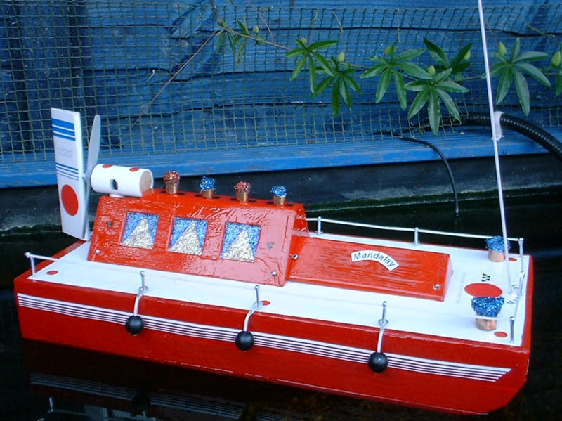
Then came the 'accessories'. I wanted something different (just like
normal) so I opted for a Canal Barge type top made of balsa and covered in
Solartrim. The two sections are joined to the deck by 4 split pins at
angles. This makes it very straightforward to remove. Pull the split pins
out and lift off the deck. A couple of runs and I wanted something new.
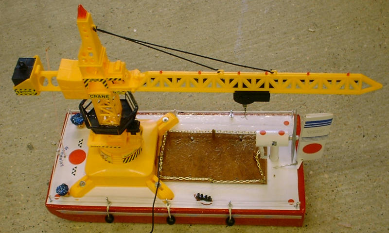
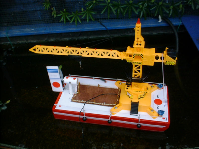
Enter the crane!!!
After scouring the internet for pictures of cranes to build one I came
across one on Ebay, already built and hard wired radio controlled and only
£19.99. It duly arrived and within hours 10'' had been taken off it's
height. it was fixed to the deck with plastic plasterboard cavity fixings,
glued with epoxy into the deck. The base of the crane was screwed down
allowing easy removal to convert it back. A piece of plastic floor tile
made the radio gear cover. I screwed eight 'posts', which came from an old
umbrella, and finished it off with light chain attached to each.
I am in the process of converting the crane from hard wired to radio
control. Quite straight forward really. There are three sticks with
forward/reverse movements. I am using three servos and each will replace
one stick. Two micro-switches are attached either side of the servo. The
servo arm, when moved left will 'switch' the up movement and when turned
right will 'switch' the down movement of the stick.
I anticipate loads of fun with this setup as my mates are already talking
about holding 'transfer' competitions on the lake. How fast can you
transfer an object between one boat and another.
There is only one thing left to work out. I want an anchor and, as I have
one channel left on my Laser 6, I have no doubt it will be achieved in the
very near future.
|